This is version 2 of Blink, where we shall see how to use a solderless breadboard to connect an LED to the Arduino. Learning to use breadboards is very fundamental to building circuits. The S4A (Scratch for Arduino) code we shall use here is exactly the same as in the previous Blink project. And the exact same blink functionality for the LED will be developed, but using a different wiring this time involving a breadboard.
Why use a breadboard? A breadboard is a quick, easy way to prototype a circuit. It allows you to experiment with electronic circuits, build and test them without any soldering. It can be used to build the simplest of circuits to very complex ones. You can read more about breadboards here and here.
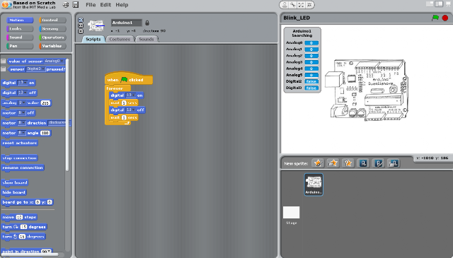
Back to Blink2... We shall connect the LED to Pin 13, just as we did in Blink version 1. The S4A code for blinking the LED turns it on and off, with an interval of 1 second, to provide the blinking effect.

Here's the wiring we shall use for Blink2 with the above S4A code:

As you can see from the image, the LED is placed on the breadboard this time, rather than connected directly to the board as in Blink version 1. We use a resistor to connect the positive leg to Pin 13. The negative leg is connected to the GND (Ground) via a jumper wire. (Both jumper wires and resistors come as part of the Arduino kit. You can also buy them in bulk at stores such as Fry's, RadioShack, Amazon, etc.)
Here, we take advantage of the fact that all the components in a row on either side of the ravine on a breadboard are electrically connected. We connect one leg of the resistor to the same row as the positive leg of the LED, and connect the other leg of the resistor to Pin 13. The resistor is used to limit the electric current flowing in to the LED, and to ensure that the LED does not burn out due to direct power from the Arduino. The jumper wire from the Arduino GND (Ground) is connected to the same row as the negative leg of the LED, to complete the circuit. The electric current will flow in to the LED from Pin 13 through the resistor and flow out to the GND (Ground), thus completing the circuit.
Now, click on the green flag on the S4A screen and watch the LED blink...
Why use a breadboard? A breadboard is a quick, easy way to prototype a circuit. It allows you to experiment with electronic circuits, build and test them without any soldering. It can be used to build the simplest of circuits to very complex ones. You can read more about breadboards here and here.
Back to Blink2... We shall connect the LED to Pin 13, just as we did in Blink version 1. The S4A code for blinking the LED turns it on and off, with an interval of 1 second, to provide the blinking effect.
Here's the wiring we shall use for Blink2 with the above S4A code:

As you can see from the image, the LED is placed on the breadboard this time, rather than connected directly to the board as in Blink version 1. We use a resistor to connect the positive leg to Pin 13. The negative leg is connected to the GND (Ground) via a jumper wire. (Both jumper wires and resistors come as part of the Arduino kit. You can also buy them in bulk at stores such as Fry's, RadioShack, Amazon, etc.)
Here, we take advantage of the fact that all the components in a row on either side of the ravine on a breadboard are electrically connected. We connect one leg of the resistor to the same row as the positive leg of the LED, and connect the other leg of the resistor to Pin 13. The resistor is used to limit the electric current flowing in to the LED, and to ensure that the LED does not burn out due to direct power from the Arduino. The jumper wire from the Arduino GND (Ground) is connected to the same row as the negative leg of the LED, to complete the circuit. The electric current will flow in to the LED from Pin 13 through the resistor and flow out to the GND (Ground), thus completing the circuit.
Now, click on the green flag on the S4A screen and watch the LED blink...

No comments:
Post a Comment